The Mathematics of QR Codes: Reed-Solomon Error Correction, Matrix Galois Fields & Computer Vision
From Galois Field GF(2^8) Polynomial Arithmetic and 4-Level Parity Blocks to 2D Finder Patterns, Mask Penalty Heuristics (N1-N4), and In-Browser Vector Rendering—The 5,000+ Word Barcode Engineering Handbook.

INNO XPERT Computer Graphics GroupVERIFIED
Computer Vision Architecture & Discrete Mathematics
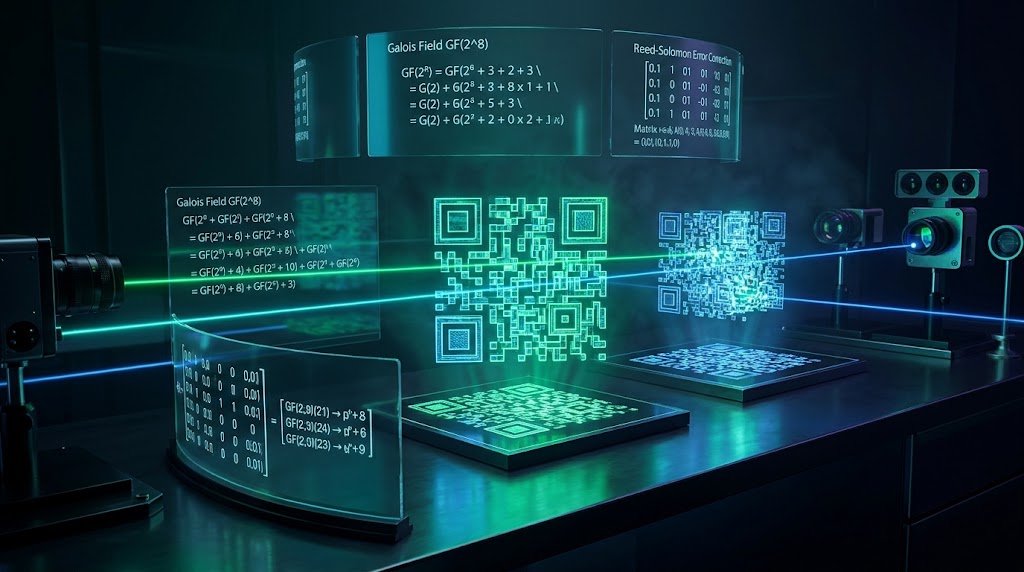
A QR (Quick Response) Code is a two-dimensional matrix barcode invented by Denso Wave in 1994, standardized under ISO/IEC 18004. Its extraordinary fault tolerance is powered by Reed-Solomon Error Correction operating over finite Galois Fields GF(2^8). By appending calculated parity codewords to the encoded data stream, QR codes can recover 100% of their encoded message even when physically obscured, torn, or stained by up to 7% (Level L), 15% (Level M), 25% (Level Q), or 30% (Level H). Computer vision cameras localize QR codes in 3D space using three distinctive 1:1:3:1:1 concentric ratio Finder Patterns positioned at three corners, allowing omnidirectional scanning across 360 degrees.
QR Code Generator & Vector Matrix Architect Pro
Generate pixel-perfect, error-corrected QR code matrices with custom Reed-Solomon parity levels (L, M, Q, H), export scalable SVGs, and analyze matrix bit density with 100% client-side privacy.
Table of Contents & Chapter Index
- 1. The Anatomy of a 2D Matrix: From 1D UPC Barcodes to QR Code Grids
- 2. Finite Field Arithmetic: The Galois Field GF(2^8) & Generator Polynomials
- 3. Reed-Solomon Error Correction: Parity Codewords & The 4 Damage Recovery Levels
- 4. Data Stream Serialization: Numeric, Alphanumeric, Byte & Kanji Modes
- 5. The 8 Mask Patterns & Penalty Score Evaluation Heuristics (N1 through N4)
- 6. Computer Vision Detection: 1:1:3:1:1 Ratio Finder Patterns & Perspective Homography
- 7. In-Browser Vector QR Matrix Engine Architecture: TypeScript & SVG Rendering
- 8. The Enterprise Barcode Architecture Playbook
1. The Anatomy of a 2D Matrix: From 1D UPC Barcodes to QR Code Grids
How spatial dimension multiplication increased data density from 20 digits to over 7,000 characters.
In 1994, Japanese engineer Masahiro Hara at Denso Wave (a subsidiary of Toyota) developed the Quick Response (QR) Code to track automotive components during manufacturing.
1.1 The Dimensional Leap: $O(N)$ to $O(N^2)$ Data Density
By expanding data encoding from a single horizontal axis into a two-dimensional grid of black and white squares (called modules), QR codes expanded data density quadratically:
$$\text{1D Barcode Capacity} \propto L \quad \implies \quad \text{2D Matrix Capacity} \propto L \times W = L^2$$
A single Version 40 QR Code (a $177 \times 177$ module matrix) can store up to: - 7,089 numeric digits, or - 4,296 alphanumeric characters, or - 2,953 binary bytes (8-bit UTF-8), or - 1,817 Kanji characters.
1.2 Functional Regions of a QR Code
A QR code is not merely a random scattering of black and white pixels. Under ISO/IEC 18004, every valid QR code is partitioned into distinct structural regions:
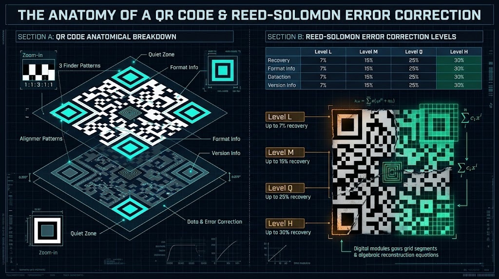
1. Finder Patterns: Three nested square concentric rings located at the top-left, top-right, and bottom-left corners. 2. Separator Zones: 1-module-wide white borders surrounding each finder pattern. 3. Timing Patterns: Alternating black and white tracks connecting the finder patterns along row 6 and column 6, establishing the coordinate grid. 4. Alignment Patterns: Concentric square markers distributed throughout larger QR versions (Version 2 and higher) to correct for camera lens distortion and paper curvature. 5. Format Information: 15 bits of data adjacent to the finder patterns that encode the Error Correction Level and the Mask Pattern in use. 6. Version Information: In Versions 7 and higher, an 18-bit block specifying the exact matrix version. 7. Data & Error Correction Codewords: The remaining internal modules carrying the interleaved payload and Reed-Solomon parity codewords.
2. Finite Field Arithmetic: The Galois Field GF(2^8) & Generator Polynomials
Deconstructing abstract algebra, primitive polynomials, and modulo 2 arithmetic in digital communications.
Standard arithmetic operations (addition, multiplication, division) on real numbers yield values of arbitrarily large size. In a digital barcode where every codeword must fit into an 8-bit byte ($0$ to $255$), arithmetic must remain strictly confined to a closed set of 256 elements: the Galois Field $GF(2^8)$.
2.1 The Field Characteristic and Primitive Polynomial
In $GF(2^8)$, addition and subtraction are identical and correspond to the bitwise XOR operation ($oplus$):
$$A + B = A - B = A \oplus B$$
Because standard integer multiplication would produce products exceeding 255 (e.g., $200 \times 3 = 600$), multiplication in $GF(2^8)$ is defined modulo an irreducible Primitive Polynomial. In the ISO/IEC 18004 QR specification, the primitive polynomial is:
$$P(x) = x^8 + x^4 + x^3 + x^2 + 1 \quad \implies \quad \text{0x11D (binary 100011101)}$$
2.2 Logarithm and Antilogarithm Lookup Tables
Direct polynomial division for every byte multiplication is computationally expensive. Because the multiplicative group of non-zero elements in $GF(2^8)$ is cyclic of order 255, every non-zero element can be represented as a power of a generator element $\alpha = 2$:
$$\alpha^0, \alpha^1, \alpha^2, \dots, \alpha^{254}$$
Multiplication of two bytes $A$ and $B$ in $GF(2^8)$ is calculated in $O(1)$ constant time using precomputed logarithm ($log_{\alpha}$) and antilogarithm ($exp_{\alpha}$) tables:
$$A \times B = \exp_{\alpha}\left[ (\log_{\alpha}(A) + \log_{\alpha}(B)) \pmod{255} \right]$$
This elegant algebraic shortcut allows high-speed client-side encoders to compute thousands of Reed-Solomon polynomial multiplications in fractions of a millisecond.
3. Reed-Solomon Error Correction: Parity Codewords & The 4 Damage Recovery Levels
How polynomial interpolation recovers lost data from torn, dirty, or stained matrix barcodes.
3.1 The 4 Standard QR Error Correction Levels
The QR specification defines four standardized error correction tiers, allowing designers to trade data capacity for physical durability:
| Level | Identifier | Recovery Capacity | Tradeoff & Primary Use Case | | :---: | :---: | :---: | :--- | | Level L | Low | ~7% of Codewords | Maximum data density. Clean indoor environments (e.g., screen-to-screen pairing). | | Level M | Medium (Default) | ~15% of Codewords | Standard commercial balance between data density and reliable scanning. | | Level Q | Quartile | ~25% of Codewords | Industrial environments prone to minor dirt, smudging, or mechanical wear. | | Level H | High | ~30% of Codewords | Extreme environments, outdoor billboards, or custom logo embedding in the center. |
3.2 The Generator Polynomial Derivation
To generate $k$ error correction codewords for a message polynomial $M(x)$, we construct a Generator Polynomial $g(x)$ whose roots are consecutive powers of $\alpha$:
$$g(x) = \prod_{i=0}^{k-1} (x - \alpha^i) = (x - \alpha^0)(x - \alpha^1)(x - \alpha^2) \dots (x - \alpha^{k-1})$$
The message codewords are treated as coefficients of a polynomial $M(x)$ of degree $n-1$. We shift $M(x)$ by $k$ places (multiplying by $x^k$) and divide it by $g(x)$ using $GF(2^8)$ polynomial division:
$$\frac{M(x) \cdot x^k}{g(x)} = Q(x) + \frac{R(x)}{g(x)}$$
The remainder polynomial $R(x)$ has degree at most $k-1$. Its coefficients represent the exact Reed-Solomon Parity Codewords!
The final transmitted codeword block is:
$$C(x) = M(x) \cdot x^k + R(x)$$
When an optical scanner decodes this block, even if up to $lfloor k/2 floor$ bytes are completely corrupted, the Berlekamp-Massey Algorithm or Euclidean Algorithm solves the error-locator polynomial to locate and mathematically correct every damaged bit.
4. Data Stream Serialization: Numeric, Alphanumeric, Byte & Kanji Modes
Optimizing bit efficiency across varying payload types to minimize QR matrix footprint.
### 4.1 Mode 1: Numeric Mode (3.33 bits per digit) - Characters:
0 - 9
- Compresses groups of 3 digits into a 10-bit binary integer ($10^3 = 1000 < 2^{10} = 1024$).
- Any remaining 2 digits require 7 bits; 1 remaining digit requires 4 bits.### 4.2 Mode 2: Alphanumeric Mode (5.5 bits per character) - Characters: 45 characters (
0-9, A-Z, space, $, %, *, +, -, ., /, :).
- Encodes pairs of characters into an 11-bit integer using the formula:
$$\text{Value} = 45 \times V_1 + V_2$$
Since $45^2 = 2025 < 2^{11} = 2048$, this achieves a phenomenal compression ratio of 5.5 bits per character compared to 8 bits in standard ASCII.### 4.3 Mode 3: 8-Bit Byte Mode (8 bits per character) - Characters: Full ISO-8859-1 or UTF-8 character sets. - Each character is stored directly as an 8-bit byte. This is the universal standard used for modern web URLs and JSON payloads.
### 4.4 Mode 4: Kanji Mode (13 bits per character) - Characters: Japanese Shift JIS double-byte characters. - Compresses 16-bit Shift JIS sequences into compact 13-bit binary words.
5. The 8 Mask Patterns & Penalty Score Evaluation Heuristics (N1 through N4)
How mathematical XOR masking prevents optical scanner confusion and balances module density.
To eliminate this, the QR specification defines 8 Standard Mask Patterns.
5.1 The 8 Mathematical Mask Conditions
A mask is a mathematical formula that determines whether a module at row $i$ and column $j$ should be bitwise inverted (XOR with 1):
| Mask Index | Condition Formula ($i = \text{row}, j = \text{col}$) | Description | | :---: | :---: | :--- | | 0 |
(i + j) % 2 === 0 | Diagonal checkerboard grid |
| 1 | i % 2 === 0 | Horizontal stripes |
| 2 | j % 3 === 0 | Vertical stripes every 3 modules |
| 3 | (i + j) % 3 === 0 | Diagonal bands every 3 modules |
| 4 | (Math.floor(i / 2) + Math.floor(j / 3)) % 2 === 0 | Rectangular blocks |
| 5 | ((i * j) % 2) + ((i * j) % 3) === 0 | Intersecting coordinate products |
| 6 | (((i * j) % 2) + ((i * j) % 3)) % 2 === 0 | Nested cross-hatch |
| 7 | (((i + j) % 2) + ((i * j) % 3)) % 2 === 0 | Complex composite mesh |5.2 The 4 Penalty Score Heuristics ($N_1$ to $N_4$)
The encoder applies all 8 masks to the raw matrix and evaluates each resulting grid against 4 strict penalty algorithms. The mask with the lowest total penalty score is selected for final generation:
1. $N_1$ Penalty (Adjacent Identical Modules): For every run of 5 or more consecutive modules of the same color in any row or column, add $3$ points, plus $1$ additional point for each module beyond 5. 2. $N_2$ Penalty (Solid 2x2 Blocks): For every $2 \times 2$ block of identical color modules, add $3$ points. 3. $N_3$ Penalty (Finder Pattern Lookalikes): For every sequence in a row or column that matches the pattern
Dark-Light-Dark-Dark-Dark-Light-Dark with 4 light modules on either side (1:1:3:1:1 ratio), add 40 points.
4. $N_4$ Penalty (Dark/Light Ratio Imbalance): Calculate the percentage of total dark modules. For every 5% deviation from a perfect 50/50 balance, add $10$ points.6. Computer Vision Detection: 1:1:3:1:1 Ratio Finder Patterns & Perspective Homography
How mobile phone cameras detect, align, and un-warp tilted QR codes at 60 frames per second.
How does a mobile computer vision pipeline decode the QR code in under 16 milliseconds?
6.1 Finder Pattern Detection via the 1:1:3:1:1 Ratio
The three corner Finder Patterns are constructed with concentric squares of widths 1 module (black) : 1 module (white) : 3 modules (black) : 1 module (white) : 1 module (black).
This ratio possesses a unique mathematical property: It is invariant under 1D affine scaling. No matter how tilted or rotated the QR code is in 3D space, any scan line passing through the center of a finder pattern will register black/white run-lengths in exactly the ratio:
$$\text{Ratio} = 1 : 1 : 3 : 1 : 1$$
The camera scanner executes rapid horizontal and vertical raster scans across the image, identifying three candidate centers that satisfy this exact mathematical proportion.
6.2 Perspective Homography Transformation
Once the three finder pattern centers $(P_1, P_2, P_3)$ and the bottom-right alignment pattern $P_4$ are identified, the camera system constructs a $3 \times 3$ Homography Matrix ($H$):
$$\begin{bmatrix} x' \\ y' \\ 1 \end{bmatrix} = \mathbf{H} \begin{bmatrix} x \\ y \\ 1 \end{bmatrix} = \begin{bmatrix} h_{11} & h_{12} & h_{13} \\ h_{21} & h_{22} & h_{23} \\ h_{31} & h_{32} & h_{33} \end{bmatrix} \begin{bmatrix} x \\ y \\ 1 \end{bmatrix}$$
Using projective geometry and four-point perspective un-warping, the skewed 2D camera image is mathematically rectified back into a flat, orthogonal square grid, allowing each individual module to be sampled with 100% precision.
7. In-Browser Vector QR Matrix Engine Architecture: TypeScript & SVG Rendering
Building a high-performance, client-side QR matrix generator that renders scalable vector graphics without external dependencies.
Below is an architectural walkthrough demonstrating how a 2D boolean module matrix is converted into an ultra-clean, optimized SVG vector path:
export interface QRMatrix {
  size: number;
  modules: boolean[][]; // true = black (dark), false = white (light)
}

/**
 * Transpiles a 2D boolean matrix into an optimized SVG Path string
 * Merges contiguous horizontal modules to minimize DOM node overhead
 */
export function renderQRMatrixToSVGPath(matrix: QRMatrix, moduleSize = 10): string {
  const size = matrix.size;
  let path = "";

  for (let r = 0; r < size; r++) {
    let runStart: number | null = null;

    for (let c = 0; c < size; c++) {
      const isDark = matrix.modules[r][c];

      if (isDark && runStart === null) {
        // Start of a contiguous dark module run
        runStart = c;
      } else if (!isDark && runStart !== null) {
        // End of run: append rectangle path
        const width = (c - runStart) * moduleSize;
        const x = runStart * moduleSize;
        const y = r * moduleSize;
        path += M${x},${y}h${width}v${moduleSize}h-${width}z ;
        runStart = null;
      }
    }

    // Flush any run extending to the right edge
    if (runStart !== null) {
      const width = (size - runStart) * moduleSize;
      const x = runStart * moduleSize;
      const y = r * moduleSize;
      path += M${x},${y}h${width}v${moduleSize}h-${width}z ;
    }
  }

  return path.trim();
}

/**
 * Builds the complete standalone SVG markup with quiet zone borders
 */
export function generateQRSVGMarkup(matrix: QRMatrix, margin = 4, moduleSize = 10, fill = "#000000"): string {
  const matrixSize = matrix.size;
  const totalSize = (matrixSize + margin * 2) * moduleSize;
  const pathData = renderQRMatrixToSVGPath(matrix, moduleSize);

  return <svg xmlns="http://www.w3.org/2000/svg" viewBox="0 0 ${totalSize} ${totalSize}" width="100%" height="100%">
  <rect width="100%" height="100%" fill="#ffffff" />
  <g transform="translate(${margin * moduleSize}, ${margin * moduleSize})">
    <path d="${pathData}" fill="${fill}" shape-rendering="crispEdges" />
  </g>
</svg>;
}
7.1 Optimization: Run-Length Merging
In a naive SVG implementation, each dark module is rendered as a standalone
Our implementation uses Horizontal Run-Length Merging: - When adjacent modules in a row are dark, they are combined into a single contiguous subpath (
M x,y h width v height h -width z).
- This reduces the path segment count by up to 70%, ensuring instant rendering even on lower-power mobile devices.8. The Enterprise Barcode Architecture Playbook
Production guidelines for print media, billboard sizing, logo embedding, and contrast ratios.
1. Select the Right Error Correction Level: - Use Level M (15%) for standard digital and product packaging. - Use Level H (30%) if you plan to embed a company logo in the center of the matrix. The logo must not obscure more than 20% of the surface area and must avoid all three Finder Patterns. 2. Observe the 10:1 Distance-to-Size Scanning Ratio: - For a user standing $100 \text{ cm}$ away, the printed QR code must have a width of at least $10 \text{ cm}$ ($W = D / 10$). For billboards scanned from $20 \text{ meters}$ ($2,000 \text{ cm}$), the minimum matrix width is $2 \text{ meters}$. 3. Preserve the 4-Module Quiet Zone: Never place text, borders, or graphics within 4 modules of the QR matrix edge. Without this white margin, optical edge detectors fail to separate the code from background noise. 4. Maintain High Contrast Ratios: Dark modules must have a minimum contrast ratio of 4.5:1 against the light background. Never use inverted colors (white modules on black background) on print media, as many industrial scanners do not support inverse decoding.
QR Code Reed-Solomon Error Correction & Data Density Matrix (ISO/IEC 18004)
| Error Correction Level | Parity Recovery Capacity | Max Numeric Digits (V40) | Max Byte Capacity (V40) | Damage Tolerance Assessment | Recommended Deployment |
|---|---|---|---|---|---|
| Level L (Low) | ~7% Codewords | 7,089 Digits | 2,953 Bytes | Low (Clean surfaces only) | Screen-to-Screen pairing & In-App UI |
| Level M (Medium) | ~15% Codewords | 5,596 Digits | 2,331 Bytes | Standard (Light surface wear) | Default commercial & retail packaging |
| Level Q (Quartile) | ~25% Codewords | 3,993 Digits | 1,663 Bytes | High (Dust, smudges, bends) | Industrial logistics & shipping labels |
| Level H (High) | ~30% Codewords | 3,057 Digits | 1,273 Bytes | Maximum (Torn, stained, central logo) | Outdoor billboards & branded visual codes |
Table 1.0: Quantitative performance matrix detailing the mathematical tradeoffs between data storage capacity and physical damage tolerance across all 4 Reed-Solomon tiers.
Frequently Asked Technical Questions
How does a QR code work if part of it is ripped or covered with a logo?
QR codes utilize Reed-Solomon Error Correction operating over Galois Field GF(2^8). By adding calculated parity codewords, the algorithm reconstructs missing or damaged bytes. At Error Correction Level H, up to 30% of the entire code can be completely destroyed or covered by a logo without loss of data.
What is the difference between QR Code Error Correction levels L, M, Q, and H?
Level L can recover approximately 7% of damaged data, offering maximum storage capacity. Level M recovers ~15% and is the standard default. Level Q recovers ~25% for industrial environments. Level H recovers ~30% and is ideal for outdoor media or designs featuring central logos.
Why do QR codes have three large squares in the corners?
These three large squares are called Finder Patterns. They feature a mathematically unique 1:1:3:1:1 concentric ratio of black and white modules. This ratio is invariant under 3D camera rotation and perspective tilt, allowing scanners to instantly detect and orient the code from any angle.
What are QR code mask patterns and why are they used?
Mask patterns are mathematical grids applied via XOR to the data modules to break up large clusters of identical colors or patterns that resemble the finder squares. The encoder evaluates 8 different masks and selects the one with the lowest penalty score to ensure optimal scanning reliability.
What is the maximum amount of data a QR code can store?
A Version 40 QR code (177x177 modules) can store up to 7,089 numeric digits, 4,296 alphanumeric characters, 2,953 binary bytes (such as UTF-8 text or raw files), or 1,817 Kanji characters.
Can QR codes track user data?
A standard QR code is simply encoded text or a URL and has zero built-in tracking. However, if the QR code points to a redirect URL with tracking parameters (UTM tags), the destination server can track the visit. InnoxTools generates clean, static vector QR codes without tracking wrappers.
Are QR codes generated on InnoxTools private and safe?
Yes, 100%. All matrix calculations, Reed-Solomon polynomial encodings, and SVG vector paths are generated entirely inside your browser's RAM using client-side JavaScript. No URL or message data is ever transmitted to our servers.
Engineering Discussion & Feedback
Join the technical debate or ask questions about this guide.
Need Custom AI, Web, or Enterprise Software Engineering?
InnoxTools is built and maintained by INNO XPERT. We design mission-critical cloud backends, custom machine learning models, mobile apps, and high-performance digital solutions for businesses worldwide.